
Analyze the problem. Analyze the flow of a falling film. Liquid flows into a reservoir and then down a flat inclined plate of length L and width W. In this situation, we will consider the viscosity and density of the liquid to be constant. The fluid is also flowing at a steady state and is under laminar flow conditions. Find the velocity distribution of this system. Ignore any entrance or exit effects. In order to properly apply the shell momentum balance procedure, the system must be under steady state and laminar flow conditions.
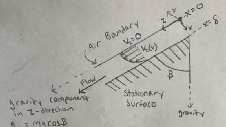
Draw a sketch of the system being analyzed to gain a better understanding of velocity distribution and flow geometry. When creating the sketch, keep several things in mind. Create a usable coordinate system. In this problem, the x-direction is origin at the top of the ramp on the surface of the fluid and the z-axis is in the same direction as the fluid’s flow. The x-direction is pointing in the direction of the ramp. Determine the component of gravity in the z-direction by using geometry. The velocity profile can also be sketched by analyzing the system and understanding boundary conditions. When on the surface of the ramp, the fluid velocity will be zero. The velocity will increase as we move further away from the surface of the ramp.
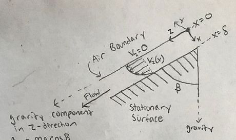
Keep in mind general rules for boundary conditions. General rules are listed below: Liquid and solid interface: the fluid velocity is equal to the velocity of the surface. Liquid and liquid interface: the tangential velocity components to the inter-facial plane are continuous through the interface, as are the molecular stresses. Liquid and gas Interface: the shear stress is taken to be zero at the inter-facial plane of the gas and liquid.System sketch_2.jpg
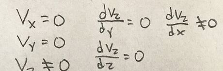
Identify zero and non-zero components of velocity of the system. Components of velocity can be determined by visualizing the flow of the system and whether the velocity or change in velocity will be zero in a certain direction. In this case, the fluid is flowing only in the z-direction and the velocity must be a function of x. This is because as x changes, so does the fluid’s velocity.
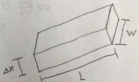
Create a “shell” diagram to show the differential element of flow. Create a “shell” or shape that matches up with the way the fluid flows. In this case, the fluid is a film and has a rectangular shape as it flows down the ramp.
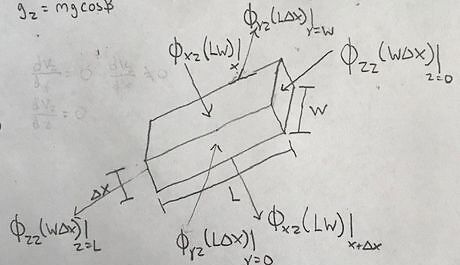
Identify all the changes in momentum occurring in the system. This can be drawn on the “shell” diagram. Momentum Flux is defined as the movement or transport of momentum through a cross-sectional area. Momentum Flux, ф, is written as ф_zz(Cross-sectional Area)|_(z=0). This represents the flux through a cross sectional area at point z=0. The first subscript z shows the direction of the change in momentum. The second subscript, z, shows the direction of fluid motion. When drawing the changes in momentum, keep in mind that momentum will change in the direction of high concentration to low concentration. Momentum is also equal to mass times velocity (p=mv). As a result, draw the momentum flux in the direction of velocity changing from high to low. It is also important to draw momentum flux through all sides of the shell. This ensures that all changes in momentum are accounted for.Shell_with_flux.jpg
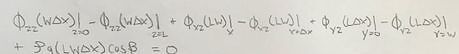
Write the momentum balance equation for the shell using the general equation form. The general form is: (Total rate of momentum transported in) – (Total rate of momentum transported out) + (Force of gravity acting on fluid) = 0.
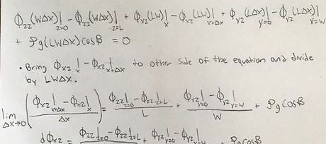
Simplify the momentum balance equation and let the thickness of the shell approach zero to obtain the differential equation of the momentum flux. Use the definition of a derivative to simplify the equation further. Just take the limit of the equation as Δx approaches zero.
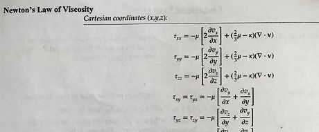
Substitute variables with those from Newton’s Law of Viscosity and eliminate any component that equals zero. Newton’s Law of Viscosity will be very helpful in determining the exact breakdown of each variable. A table of the breakdown of the total momentum flux tensor will also be very useful for this same task.Law of viscosity.jpg Use the charts above to substitute values in and cancel out components that are equal to zero. The results are shown below.Flux breakdown results.jpg Substitute these simplified values into the differential equation and simplify further. Notice that the total pressure at z=0 and z=L are the same. This is because the film is exposed to the atmosphere and atmospheric pressure is the same at all points along the film.Shear stress derivative.jpg
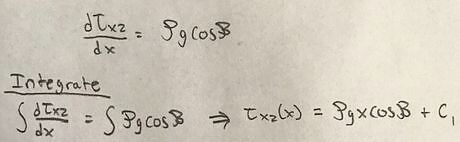
Integrate the equation to determine a general form of shear stress. Integrating the differential equation results in a general equation for shear stress.
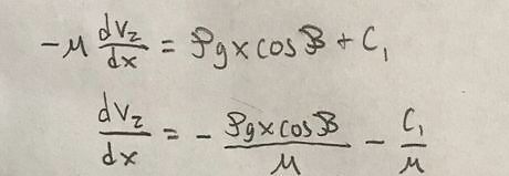
Substitute values of shear stress for the differential equation of velocity. The equivalent values for shear stress can be found using the tables above.
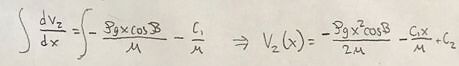
Integrate the equation to determine a general solution to the velocity distribution. This integration results in general solution to the velocity equation.
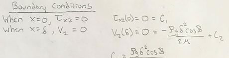
Determine the boundary conditions of the system. When looking at the sketch of the system, we can see that when x = 0, the fluid is bordering a liquid-gas interface. As a result, the shear stress at the boundary must be zero. When x = δ, the fluid is bordering the solid ramp. As a result, the velocity at this boundary must be zero because the solid surface is stationary.

Apply the boundary conditions to solve for unknown constants in the velocity distribution equation. Plug these values into both the general forms of the shear stress and velocity equations and solve for C_1and C_2.
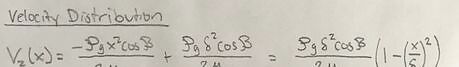
Insert constant values into general velocity equation to determine the final velocity distribution. Plug the C_1 and C_2 values back into the general velocity equation. You can then simplify this equation to determine the velocity distribution of the liquid film as it flows down the inclined plate.


Comments
0 comment